1. The surface of the commutator is obviously uneven (can be touched by hand) or the spark when the motor is running is as in the fourth case. At this time, it is necessary to disassemble the armature and use a precision machine tool to process the converter;
2. Basically flat, but with very small scars or sparks, such as water sandpaper, manual grinding and grinding without disassembling the armature.
The grinding sequence is first to press the outer arc of the commutator, process a wooden tool, cut several water sandpapers of different thicknesses into strips as wide as the commutator, and remove the carbon brush (please note Mark the handle of the removed carbon brush and the groove of the carbon brush to ensure that the left and right are not wrongly changed during installation) Use a wooden tool wrapped with sandpaper to stick the commutator, and press the rotation direction of the motor with the other hand, Slightly turn the shaft commutator to grind. The order of the thickness of the sandpaper used in the maintenance of the AC servo motor is: first thick and then fine. When one piece of sandpaper is unusable, change to another finer sandpaper until the finest water sandpaper (or metallographic sandpaper) is used up.
The phase of the UVW electronic commutation signal of the incremental encoder with the commutation signal and the phase of the rotor magnetic pole, or the phase of the electrical angle is aligned as follows:
(1) Use a DC power supply to supply a DC power less than the rated current to the UV winding of the motor, U in, V out, and orient the motor shaft to a balanced position;
(2) Observe the U-phase signal and Z signal of the encoder with an oscilloscope;
(3) Adjust the relative position of the encoder shaft and the motor shaft;
(4) While adjusting, observe the transition edge of the U-phase signal of the encoder and the Z signal until the Z signal is stable at a high level (the default state of the Z signal is low level), lock the relative positional relationship of the motor between the encoder and the AC servo;
(5) Twist the motor shaft back and forth. After letting go, if the Z signal can be stabilized at a high level every time the motor shaft freely returns to the equilibrium position, the alignment is valid.
The phase alignment of the absolute encoder is not much different for single-turn and multi-turn. At present, a very practical method is to use the EEPROM inside the encoder to store the phase measured after the encoder is randomly installed on the motor shaft. The specific method is as follows:
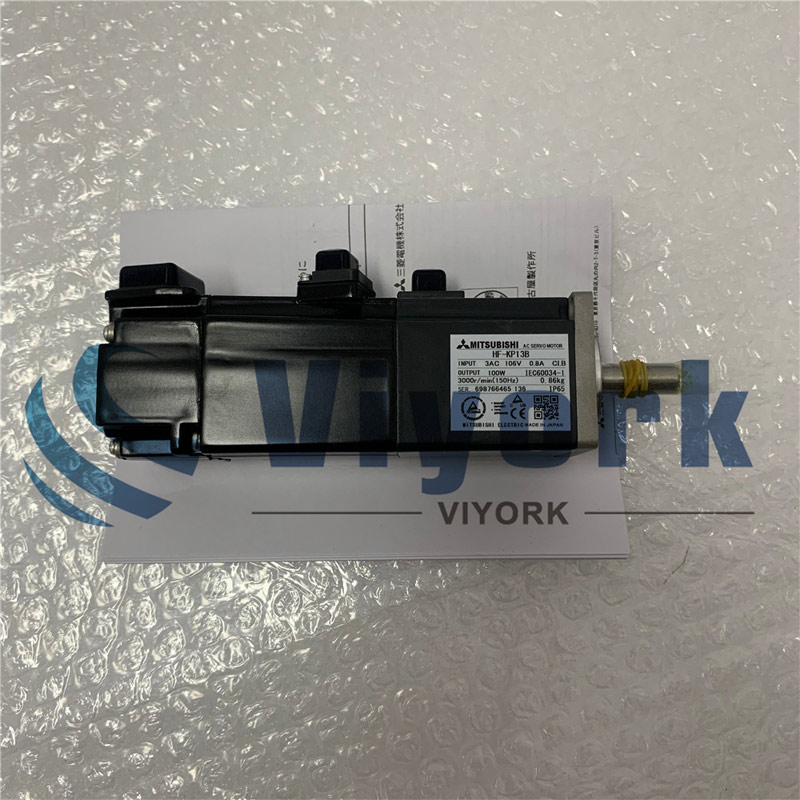
(1) Randomly install the encoder on the AC servo motor, eg. mitsubishi ac servo motor. That means, it need consolidate the encoder shaft and the motor shaft, as well as the encoder shell and the motor shell;
(2) Use a DC power supply to supply a DC power less than the rated current to the UV winding of the motor, U in, V out, and orient the motor shaft to a balanced position;
(3) Use the servo driver to read the single-turn position value of the absolute encoder, and store it in the EEPROM inside the encoder that records the initial phase of the electrical angle of the motor;
(4) The alignment process ends.
 Call us on:
  Email Us:
  1103, Block C, South Building, Luo Fang Road, Luohu District, Shenzhen, 518001, China
